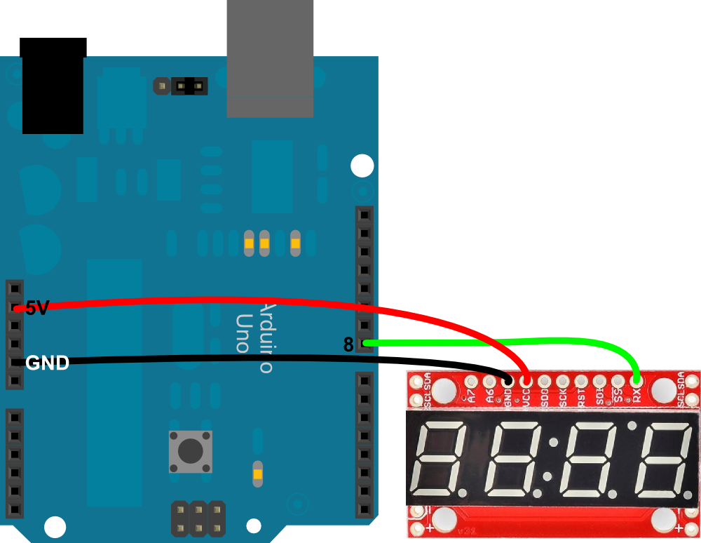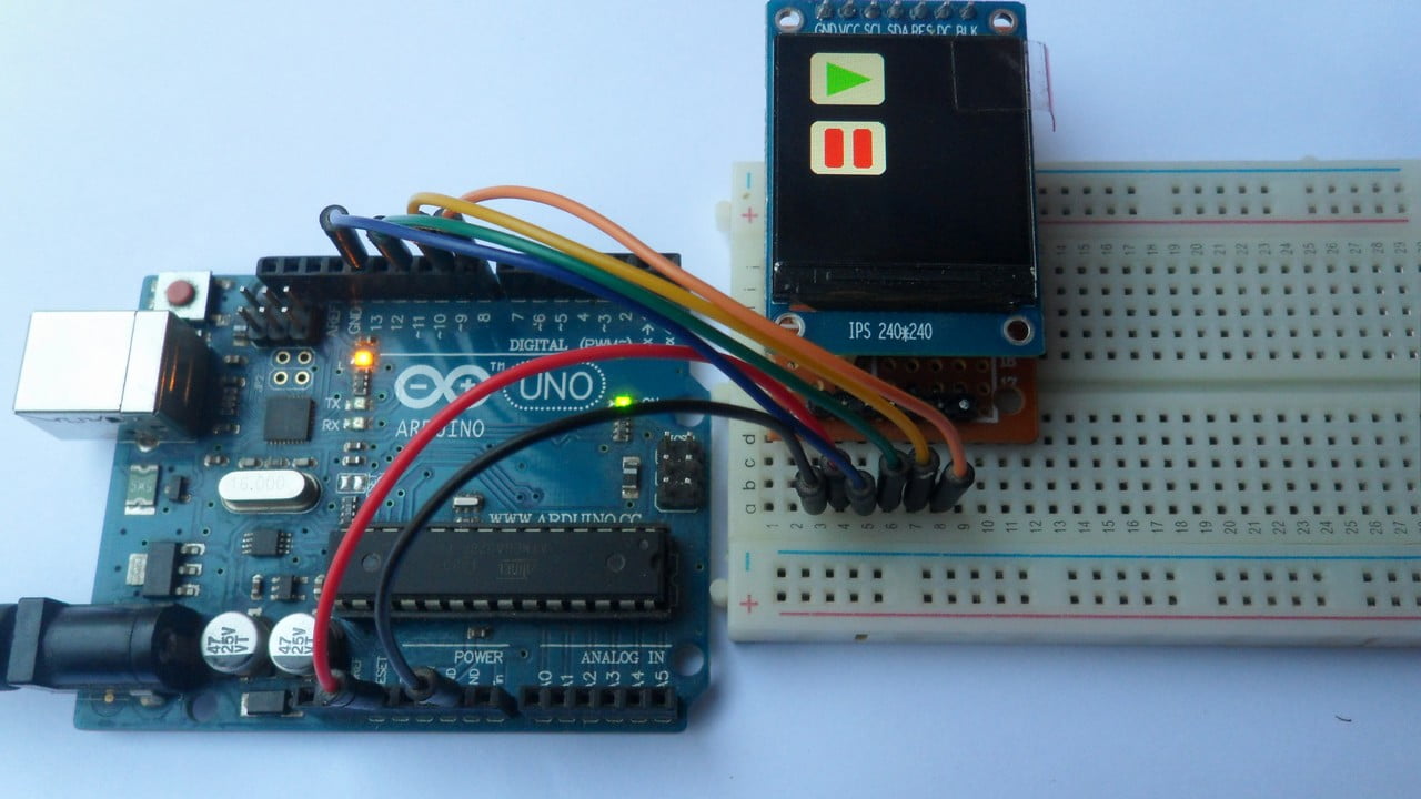
The shorter of the two legs, towards the flat edge of the bulb indicates the negative terminal.Wiring TM1637 Module with Arduino UNO. Note To find out the polarity of an LED, look at it closely. Follow the circuit diagram and hook up the components on the breadboard as shown in the image given below. 1 × Breadboard 1 × Arduino Uno R3 1 × LED 2 × Jumper Procedure.
Check the wiring diagram below and the pinout table from the introduction of this article. In order to control the LCD and display characters, you will need to add a few extra connections. How to connect the LCD to Arduino UNO. The LCD has 16 connection pins, numbered 1-16 from left to right. It is easier to use than other types of Arduino Boards.16×2 LCD pinout. You only need to connect four wires: two for power and other the two.The Arduino UNO is a standard board of Arduino, which is based on an ATmega328P microcontroller.
The processor core inside it is of 8-bit. ATmega328 Microcontroller- It is a single chip Microcontroller of the ATmel family. This Arduino UNO Pinout diagram reference will hopefully help you get the most.
The TXD is used for transmitting the data, and RXD is used for receiving the data. The ground pins are used to ground the circuit.TXD and RXD pins are used for serial communication. For any changes in the input voltage of the regulator, the output voltage is constant and steady. The primary function of voltage regulator is to regulate the voltage level in the Arduino board. The Arduino UNO and Nano models are based on the ATmega328 Microcontroller.The voltage regulator converts the input voltage to 5V.


It is defined as the line that carries the clock data. It is called as a data line, while SCL is called as a clock line.It stands for Serial Clock. It is a line used by the slave and master to send and receive data.
It acts as the enable line.It is the two-wire serial communication protocol. It is the Slave Select line, which is used by the master. It uses conductors for data receiving, data sending, synchronization, and device selection (for communication).It stands for Master Output/ Slave Input.The MOSI and SCK are driven by the Master.It stands for Slave Select. It is popularly used by the microcontrollers to communicate with one or more peripheral devices quickly. The Serial Clock is generated by the device and it is called as master.It stands for Serial Peripheral Interface.
The I2C is a serial communication protocol that uses SCL (Serial Clock) and SDA (Serial Data) to receive and send data between two devices.3.3V and 5V are the operating voltages of the board.


 0 kommentar(er)
